
Schematic diagram of liquid-cooled solar container
As the photovoltaic (PV) industry continues to evolve, advancements in Schematic diagram of liquid-cooled solar container have become critical to optimizing the utilization of renewable energy sources. From innovative battery technologies to intelligent energy management systems, these solutions are transforming the way we store and distribute solar-generated electricity.
6 FAQs about [Schematic diagram of liquid-cooled solar container]
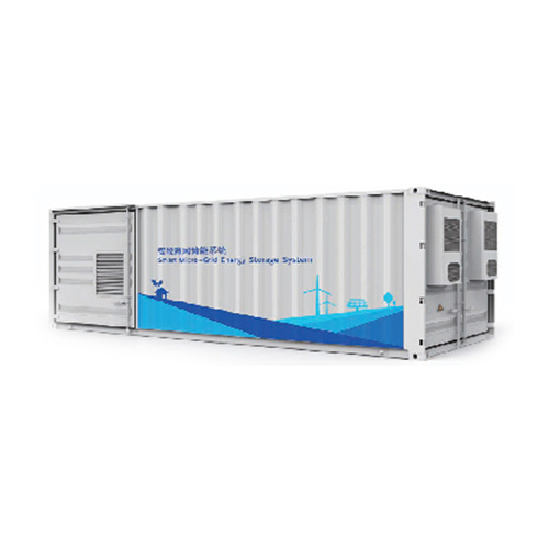
What is the user manual for liquid-cooled energy storage system?5.01MWh User Manual for liquid-cooled ESS 1.Summary 1.1 Overall Summarize This manual mainly introduces our product, transportation, installation, operation, maintenance and troubleshooting of the 20' Standard Liquid-cooled Energy Storage System.
What should I know before using Dard liquid-cooled energy storage system?dard Liquid-cooled Energy Storage System. Before using this product, please be sure to read this manual carefully and operate the energy storage system according to the methods described in this manual, otherwise may le d regulations when this product is used;Have a good understanding of the terms and conditions of this manual, with professional
What is a 5MWh liquid-cooling energy storage system?The 5MWh liquid-cooling energy storage system comprises cells, BMS, a 20’GP container, thermal management system, firefighting system, bus unit, power distribution unit, wiring harness, and more. And, the container offers a protective capability and serves as a transportable workspace for equipment operation.
What is a liquid cooling thermal management system?The liquid cooling thermal management system for the energy storage cabin includes liquid cooling units, liquid cooling pipes, and coolant. The unit achieves cooling or heating of the coolant through thermal exchange. The coolant transports heat via thermal exchange with the cooling plates and the liquid cooling units.
What is a liquid cooling unit?The product installs a liquid-cooling unit for thermal management of energy storage battery system. It effectively dissipates excess heat in high-temperature environments while in low temperatures, it preheats the equipment. Such measures ensure that the equipment within the cabin maintains its lifespan.
How does a liquid cooling unit work?3.12.1.3 The design of the liquid cooling unit must align with the cabin structure, adequately addressing dust prevention needed in the operating environment. The liquid cooling pipeline operates in a closed loop. The coolant, propelled by a pump, circulates through the cold plate, exchanging heat with the batteries, which raises its temperature.
Related Contents
-
Schematic diagram of vanadium liquid flow battery solar container system
-
Solar container inverter electrical schematic diagram
-
Schematic diagram of the principle of liquid flow battery solar container technology
-
Schematic diagram of electric solar container control mechanism
-
Schematic diagram of multiple off-grid solar container systems
-
Schematic diagram of compressed air solar container power generation system
List of relevant information about Schematic diagram of liquid-cooled solar container
Schematic of the solar assisted liquid desiccant system with
Fig. 1. Schematic of a desiccant cooling air conditioning [8]. Fig. 2. Moisture removal process by desiccant [6]. Fig. 3. Schematic diagram of solar air pre-treatment collector/regenerator [15]. Fig. 4.
Cooling system analysis for a data center using liquid immersed servers
Fig. 1 Schematic diagram of the data center cooling system The model using COMSOL is applied to simulate the heat transfer at the server level only. However, the data of dry cooler and buffer heat
Study on uniform distribution of liquid cooling pipeline in container
The above studies have explored the flow uniformity of liquid cooling plates, but in the BESS liquid-cooling system, the flow uniformity of the primary, secondary, and tertiary pipelines
Utility-scale battery energy storage system (BESS)
Battery storage systems are emerging as one of the potential solutions to increase power system flexibility in the presence of variable energy resources, such as solar and wind, due to their unique
Schematic diagram of liquid cooling energy storage outdoor cabinet
Download scientific diagram | electrical schematic diagram of cooling water system. from publication: Research on building energy management in HVAC control system for university
Immersion liquid cooling for electronics: Materials, systems
The current work systematically reviews the research progress on immersion cooling technology in electronic device thermal management, including the properties of immersion coolants,
Liquid Cooling BESS Container, 5MWH Container Energy Storage
Designed for efficiency and ease of use, this energy storage container system offers minimalist operation and maintenance, making it an attractive choice for industries that prioritize cost-effectiveness.
Schematic diagram of hybrid solar absorption-cooling and.
In another study by Velázquez-Limón et al. [36], a solar hybrid system of H 2 O-LiBr absorption cooling and flash seawater desalination is studied with 2406 kg of daily water production, yet no
Contact Integrated Localized Bess Provider
Enter your inquiry details, We will reply you in 24 hours.
5.01MWh User Manual for liquid-cooled ESS 1.Summary 1.1 Overall Summarize This manual mainly introduces our product, transportation, installation, operation, maintenance and troubleshooting of the 20' Standard Liquid-cooled Energy Storage System.
What should I know before using Dard liquid-cooled energy storage system?dard Liquid-cooled Energy Storage System. Before using this product, please be sure to read this manual carefully and operate the energy storage system according to the methods described in this manual, otherwise may le d regulations when this product is used;Have a good understanding of the terms and conditions of this manual, with professional
What is a 5MWh liquid-cooling energy storage system?The 5MWh liquid-cooling energy storage system comprises cells, BMS, a 20’GP container, thermal management system, firefighting system, bus unit, power distribution unit, wiring harness, and more. And, the container offers a protective capability and serves as a transportable workspace for equipment operation.
What is a liquid cooling thermal management system?The liquid cooling thermal management system for the energy storage cabin includes liquid cooling units, liquid cooling pipes, and coolant. The unit achieves cooling or heating of the coolant through thermal exchange. The coolant transports heat via thermal exchange with the cooling plates and the liquid cooling units.
What is a liquid cooling unit?The product installs a liquid-cooling unit for thermal management of energy storage battery system. It effectively dissipates excess heat in high-temperature environments while in low temperatures, it preheats the equipment. Such measures ensure that the equipment within the cabin maintains its lifespan.
How does a liquid cooling unit work?3.12.1.3 The design of the liquid cooling unit must align with the cabin structure, adequately addressing dust prevention needed in the operating environment. The liquid cooling pipeline operates in a closed loop. The coolant, propelled by a pump, circulates through the cold plate, exchanging heat with the batteries, which raises its temperature.
Related Contents
-
Schematic diagram of vanadium liquid flow battery solar container system
-
Solar container inverter electrical schematic diagram
-
Schematic diagram of the principle of liquid flow battery solar container technology
-
Schematic diagram of electric solar container control mechanism
-
Schematic diagram of multiple off-grid solar container systems
-
Schematic diagram of compressed air solar container power generation system
List of relevant information about Schematic diagram of liquid-cooled solar container
Schematic of the solar assisted liquid desiccant system with
Fig. 1. Schematic of a desiccant cooling air conditioning [8]. Fig. 2. Moisture removal process by desiccant [6]. Fig. 3. Schematic diagram of solar air pre-treatment collector/regenerator [15]. Fig. 4.
Cooling system analysis for a data center using liquid immersed servers
Fig. 1 Schematic diagram of the data center cooling system The model using COMSOL is applied to simulate the heat transfer at the server level only. However, the data of dry cooler and buffer heat
Study on uniform distribution of liquid cooling pipeline in container
The above studies have explored the flow uniformity of liquid cooling plates, but in the BESS liquid-cooling system, the flow uniformity of the primary, secondary, and tertiary pipelines
Utility-scale battery energy storage system (BESS)
Battery storage systems are emerging as one of the potential solutions to increase power system flexibility in the presence of variable energy resources, such as solar and wind, due to their unique
Schematic diagram of liquid cooling energy storage outdoor cabinet
Download scientific diagram | electrical schematic diagram of cooling water system. from publication: Research on building energy management in HVAC control system for university
Immersion liquid cooling for electronics: Materials, systems
The current work systematically reviews the research progress on immersion cooling technology in electronic device thermal management, including the properties of immersion coolants,
Liquid Cooling BESS Container, 5MWH Container Energy Storage
Designed for efficiency and ease of use, this energy storage container system offers minimalist operation and maintenance, making it an attractive choice for industries that prioritize cost-effectiveness.
Schematic diagram of hybrid solar absorption-cooling and.
In another study by Velázquez-Limón et al. [36], a solar hybrid system of H 2 O-LiBr absorption cooling and flash seawater desalination is studied with 2406 kg of daily water production, yet no
Contact Integrated Localized Bess Provider
Enter your inquiry details, We will reply you in 24 hours.
dard Liquid-cooled Energy Storage System. Before using this product, please be sure to read this manual carefully and operate the energy storage system according to the methods described in this manual, otherwise may le d regulations when this product is used;Have a good understanding of the terms and conditions of this manual, with professional
What is a 5MWh liquid-cooling energy storage system?The 5MWh liquid-cooling energy storage system comprises cells, BMS, a 20’GP container, thermal management system, firefighting system, bus unit, power distribution unit, wiring harness, and more. And, the container offers a protective capability and serves as a transportable workspace for equipment operation.
What is a liquid cooling thermal management system?The liquid cooling thermal management system for the energy storage cabin includes liquid cooling units, liquid cooling pipes, and coolant. The unit achieves cooling or heating of the coolant through thermal exchange. The coolant transports heat via thermal exchange with the cooling plates and the liquid cooling units.
What is a liquid cooling unit?The product installs a liquid-cooling unit for thermal management of energy storage battery system. It effectively dissipates excess heat in high-temperature environments while in low temperatures, it preheats the equipment. Such measures ensure that the equipment within the cabin maintains its lifespan.
How does a liquid cooling unit work?3.12.1.3 The design of the liquid cooling unit must align with the cabin structure, adequately addressing dust prevention needed in the operating environment. The liquid cooling pipeline operates in a closed loop. The coolant, propelled by a pump, circulates through the cold plate, exchanging heat with the batteries, which raises its temperature.
Related Contents
-
Schematic diagram of vanadium liquid flow battery solar container system
-
Solar container inverter electrical schematic diagram
-
Schematic diagram of the principle of liquid flow battery solar container technology
-
Schematic diagram of electric solar container control mechanism
-
Schematic diagram of multiple off-grid solar container systems
-
Schematic diagram of compressed air solar container power generation system
List of relevant information about Schematic diagram of liquid-cooled solar container
Schematic of the solar assisted liquid desiccant system with
Fig. 1. Schematic of a desiccant cooling air conditioning [8]. Fig. 2. Moisture removal process by desiccant [6]. Fig. 3. Schematic diagram of solar air pre-treatment collector/regenerator [15]. Fig. 4.
Cooling system analysis for a data center using liquid immersed servers
Fig. 1 Schematic diagram of the data center cooling system The model using COMSOL is applied to simulate the heat transfer at the server level only. However, the data of dry cooler and buffer heat
Study on uniform distribution of liquid cooling pipeline in container
The above studies have explored the flow uniformity of liquid cooling plates, but in the BESS liquid-cooling system, the flow uniformity of the primary, secondary, and tertiary pipelines
Utility-scale battery energy storage system (BESS)
Battery storage systems are emerging as one of the potential solutions to increase power system flexibility in the presence of variable energy resources, such as solar and wind, due to their unique
Schematic diagram of liquid cooling energy storage outdoor cabinet
Download scientific diagram | electrical schematic diagram of cooling water system. from publication: Research on building energy management in HVAC control system for university
Immersion liquid cooling for electronics: Materials, systems
The current work systematically reviews the research progress on immersion cooling technology in electronic device thermal management, including the properties of immersion coolants,
Liquid Cooling BESS Container, 5MWH Container Energy Storage
Designed for efficiency and ease of use, this energy storage container system offers minimalist operation and maintenance, making it an attractive choice for industries that prioritize cost-effectiveness.
Schematic diagram of hybrid solar absorption-cooling and.
In another study by Velázquez-Limón et al. [36], a solar hybrid system of H 2 O-LiBr absorption cooling and flash seawater desalination is studied with 2406 kg of daily water production, yet no
Contact Integrated Localized Bess Provider
Enter your inquiry details, We will reply you in 24 hours.
The 5MWh liquid-cooling energy storage system comprises cells, BMS, a 20’GP container, thermal management system, firefighting system, bus unit, power distribution unit, wiring harness, and more. And, the container offers a protective capability and serves as a transportable workspace for equipment operation.
What is a liquid cooling thermal management system?The liquid cooling thermal management system for the energy storage cabin includes liquid cooling units, liquid cooling pipes, and coolant. The unit achieves cooling or heating of the coolant through thermal exchange. The coolant transports heat via thermal exchange with the cooling plates and the liquid cooling units.
What is a liquid cooling unit?The product installs a liquid-cooling unit for thermal management of energy storage battery system. It effectively dissipates excess heat in high-temperature environments while in low temperatures, it preheats the equipment. Such measures ensure that the equipment within the cabin maintains its lifespan.
How does a liquid cooling unit work?3.12.1.3 The design of the liquid cooling unit must align with the cabin structure, adequately addressing dust prevention needed in the operating environment. The liquid cooling pipeline operates in a closed loop. The coolant, propelled by a pump, circulates through the cold plate, exchanging heat with the batteries, which raises its temperature.
Related Contents
-
Schematic diagram of vanadium liquid flow battery solar container system
-
Solar container inverter electrical schematic diagram
-
Schematic diagram of the principle of liquid flow battery solar container technology
-
Schematic diagram of electric solar container control mechanism
-
Schematic diagram of multiple off-grid solar container systems
-
Schematic diagram of compressed air solar container power generation system
List of relevant information about Schematic diagram of liquid-cooled solar container
Schematic of the solar assisted liquid desiccant system with
Fig. 1. Schematic of a desiccant cooling air conditioning [8]. Fig. 2. Moisture removal process by desiccant [6]. Fig. 3. Schematic diagram of solar air pre-treatment collector/regenerator [15]. Fig. 4.
Cooling system analysis for a data center using liquid immersed servers
Fig. 1 Schematic diagram of the data center cooling system The model using COMSOL is applied to simulate the heat transfer at the server level only. However, the data of dry cooler and buffer heat
Study on uniform distribution of liquid cooling pipeline in container
The above studies have explored the flow uniformity of liquid cooling plates, but in the BESS liquid-cooling system, the flow uniformity of the primary, secondary, and tertiary pipelines
Utility-scale battery energy storage system (BESS)
Battery storage systems are emerging as one of the potential solutions to increase power system flexibility in the presence of variable energy resources, such as solar and wind, due to their unique
Schematic diagram of liquid cooling energy storage outdoor cabinet
Download scientific diagram | electrical schematic diagram of cooling water system. from publication: Research on building energy management in HVAC control system for university
Immersion liquid cooling for electronics: Materials, systems
The current work systematically reviews the research progress on immersion cooling technology in electronic device thermal management, including the properties of immersion coolants,
Liquid Cooling BESS Container, 5MWH Container Energy Storage
Designed for efficiency and ease of use, this energy storage container system offers minimalist operation and maintenance, making it an attractive choice for industries that prioritize cost-effectiveness.
Schematic diagram of hybrid solar absorption-cooling and.
In another study by Velázquez-Limón et al. [36], a solar hybrid system of H 2 O-LiBr absorption cooling and flash seawater desalination is studied with 2406 kg of daily water production, yet no
The liquid cooling thermal management system for the energy storage cabin includes liquid cooling units, liquid cooling pipes, and coolant. The unit achieves cooling or heating of the coolant through thermal exchange. The coolant transports heat via thermal exchange with the cooling plates and the liquid cooling units.
What is a liquid cooling unit?The product installs a liquid-cooling unit for thermal management of energy storage battery system. It effectively dissipates excess heat in high-temperature environments while in low temperatures, it preheats the equipment. Such measures ensure that the equipment within the cabin maintains its lifespan.
How does a liquid cooling unit work?3.12.1.3 The design of the liquid cooling unit must align with the cabin structure, adequately addressing dust prevention needed in the operating environment. The liquid cooling pipeline operates in a closed loop. The coolant, propelled by a pump, circulates through the cold plate, exchanging heat with the batteries, which raises its temperature.
Related Contents
-
Schematic diagram of vanadium liquid flow battery solar container system
-
Solar container inverter electrical schematic diagram
-
Schematic diagram of the principle of liquid flow battery solar container technology
-
Schematic diagram of electric solar container control mechanism
-
Schematic diagram of multiple off-grid solar container systems
-
Schematic diagram of compressed air solar container power generation system
List of relevant information about Schematic diagram of liquid-cooled solar container
Schematic of the solar assisted liquid desiccant system with
Fig. 1. Schematic of a desiccant cooling air conditioning [8]. Fig. 2. Moisture removal process by desiccant [6]. Fig. 3. Schematic diagram of solar air pre-treatment collector/regenerator [15]. Fig. 4.
Cooling system analysis for a data center using liquid immersed servers
Fig. 1 Schematic diagram of the data center cooling system The model using COMSOL is applied to simulate the heat transfer at the server level only. However, the data of dry cooler and buffer heat
Study on uniform distribution of liquid cooling pipeline in container
The above studies have explored the flow uniformity of liquid cooling plates, but in the BESS liquid-cooling system, the flow uniformity of the primary, secondary, and tertiary pipelines
Utility-scale battery energy storage system (BESS)
Battery storage systems are emerging as one of the potential solutions to increase power system flexibility in the presence of variable energy resources, such as solar and wind, due to their unique
Schematic diagram of liquid cooling energy storage outdoor cabinet
Download scientific diagram | electrical schematic diagram of cooling water system. from publication: Research on building energy management in HVAC control system for university
Immersion liquid cooling for electronics: Materials, systems
The current work systematically reviews the research progress on immersion cooling technology in electronic device thermal management, including the properties of immersion coolants,
Liquid Cooling BESS Container, 5MWH Container Energy Storage
Designed for efficiency and ease of use, this energy storage container system offers minimalist operation and maintenance, making it an attractive choice for industries that prioritize cost-effectiveness.
Schematic diagram of hybrid solar absorption-cooling and.
In another study by Velázquez-Limón et al. [36], a solar hybrid system of H 2 O-LiBr absorption cooling and flash seawater desalination is studied with 2406 kg of daily water production, yet no
The product installs a liquid-cooling unit for thermal management of energy storage battery system. It effectively dissipates excess heat in high-temperature environments while in low temperatures, it preheats the equipment. Such measures ensure that the equipment within the cabin maintains its lifespan.
How does a liquid cooling unit work?3.12.1.3 The design of the liquid cooling unit must align with the cabin structure, adequately addressing dust prevention needed in the operating environment. The liquid cooling pipeline operates in a closed loop. The coolant, propelled by a pump, circulates through the cold plate, exchanging heat with the batteries, which raises its temperature.
Related Contents
-
Schematic diagram of vanadium liquid flow battery solar container system
-
Solar container inverter electrical schematic diagram
-
Schematic diagram of the principle of liquid flow battery solar container technology
-
Schematic diagram of electric solar container control mechanism
-
Schematic diagram of multiple off-grid solar container systems
-
Schematic diagram of compressed air solar container power generation system
3.12.1.3 The design of the liquid cooling unit must align with the cabin structure, adequately addressing dust prevention needed in the operating environment. The liquid cooling pipeline operates in a closed loop. The coolant, propelled by a pump, circulates through the cold plate, exchanging heat with the batteries, which raises its temperature.
List of relevant information about Schematic diagram of liquid-cooled solar container
Schematic of the solar assisted liquid desiccant system with
Fig. 1. Schematic of a desiccant cooling air conditioning [8]. Fig. 2. Moisture removal process by desiccant [6]. Fig. 3. Schematic diagram of solar air pre-treatment collector/regenerator [15]. Fig. 4.
Cooling system analysis for a data center using liquid immersed servers
Fig. 1 Schematic diagram of the data center cooling system The model using COMSOL is applied to simulate the heat transfer at the server level only. However, the data of dry cooler and buffer heat
Study on uniform distribution of liquid cooling pipeline in container
The above studies have explored the flow uniformity of liquid cooling plates, but in the BESS liquid-cooling system, the flow uniformity of the primary, secondary, and tertiary pipelines
Utility-scale battery energy storage system (BESS)
Battery storage systems are emerging as one of the potential solutions to increase power system flexibility in the presence of variable energy resources, such as solar and wind, due to their unique
Schematic diagram of liquid cooling energy storage outdoor cabinet
Download scientific diagram | electrical schematic diagram of cooling water system. from publication: Research on building energy management in HVAC control system for university
Immersion liquid cooling for electronics: Materials, systems
The current work systematically reviews the research progress on immersion cooling technology in electronic device thermal management, including the properties of immersion coolants,
Liquid Cooling BESS Container, 5MWH Container Energy Storage
Designed for efficiency and ease of use, this energy storage container system offers minimalist operation and maintenance, making it an attractive choice for industries that prioritize cost-effectiveness.
Schematic diagram of hybrid solar absorption-cooling and.
In another study by Velázquez-Limón et al. [36], a solar hybrid system of H 2 O-LiBr absorption cooling and flash seawater desalination is studied with 2406 kg of daily water production, yet no
Contact Integrated Localized Bess Provider
Enter your inquiry details, We will reply you in 24 hours.